Pre-engineered building
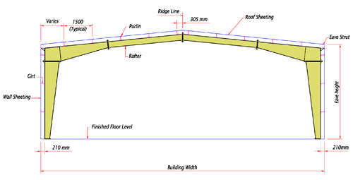
Pre-engineered buildings are defined by the following geometrical parameters: Building width, Length, Eave height, Roof slope, Sidewall bay spacing, end wall bay spacing and main frame module space. Also design loads are the basic parameter.
Building Length and width are defined by the distance between steel lines. Extreme surface edges of girts and purlins are treated as steel line. Sum of side wall bay spaces will be equal to the building length.
Eave height is the distance from Finished floor level to inter section point of roof and sidewall steel line.
Roof Slope is defined as the ratio between vertical distance and horizontal distance of the roof surface. Standard roof slopes are 0.5:10 and 1.0:10
To describe the side wall bay spacing, main frame column spacing to be referred start from back end wall steel line to right end wall steel line. Same way back end wall and front end wall bay spacing to be given from left side wall steel line to right side wall steel line.

Primary Main frames:
Pre-engineered buildings offer complete freedom of design to accommodate customers need. EBS has particularly developed several types to offer optimized economical configuration for customers to choose from according to space, span, crane and architectural requirements.
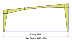
Frame
When building width is less than 25m, clear span frame will provide un-interrupted clear work space in the building. When building width is more than 25m, it will not be an economical choice to the customer.
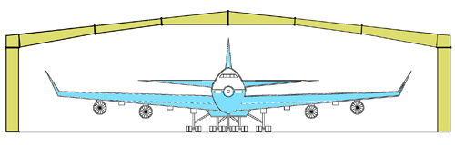
Airport Hangers
The width of the buildings may vary from 30m to 90m depending upon the number and type of aircraft. Hangers up to 60m clear span are economically built using pre-engineering building system; however, for span exceeding 60m, a structural truss-column system becomes more economical.
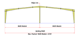
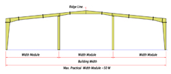
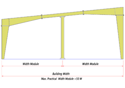
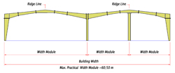
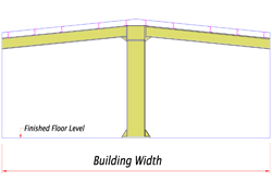
Multi span Frame
The introduction of interior columns allows for greater spans without internal gutters and rainwater pipes. This type of design optimizes bay spacing, building weight and therefore cost.
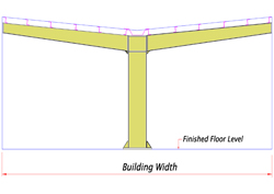
Single Slope buildings are offered with single or multi-span modular options. Straight or tapered columns are available.
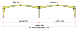
Multi Gable Buildings are maintaining a low ridge height for very wide buildings.
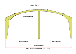
Curved Roof gives special appearance to the building and modular width also can be increased.

Roof system
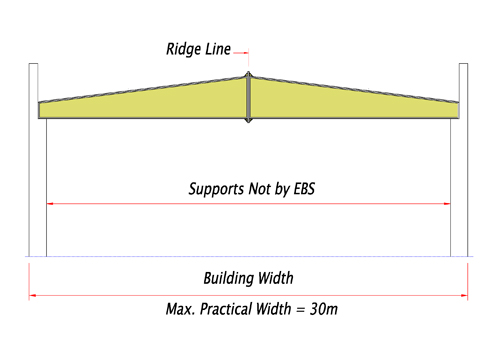
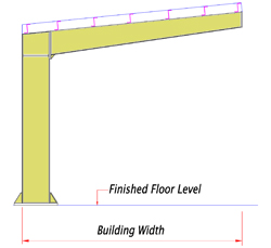
When Concrete wall exist to support main building, utilizing the support, roof system will be the cost effective solution and more work space to the client can be achieved. However, there will be a limitation on building span.
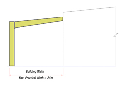
Car Canopies
These building enhancements are ideal for car parking, building expansions. The structure can be made of hot-rolled or built-up sections. Lean-to’s require a supporting structure to take the lean-to reaction.
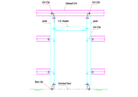
Secondary end wall Frame:
Simple end wall frame with pin connected rafter and columns will reduce the building weight and on cost. However, if future expansion of the building is expected along sidewall, Rigid frame should be used @ ends. Standard endwall column spacing would be 6 mts. Endwall column and rafter can be made from hot-rolled, built-up or cold form cee section. Flush girt are standard feature for end wall.
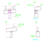
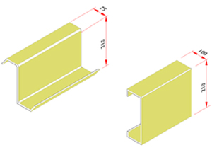
Cold form structure:
Supporting members for wall and roof panels are girt and purlins. Cold form Zee section is used as purlin and girt. Standard height of Zee and Cee sections are 210mm. However EBS can supply any depth of Zee and Cee sections ranging from 125mm to 300mm. Cee sections are widely used as frame open members; jamb, header and sills. Also Cee section is used as end wall column and rafter. Main advantage on cold form members are
- 1. As raw material is pre-galvanized, no painting is required and self rust proofing.
- 2. There is no welding involved in the members and production is automated, hence accurate and faster supply of final product is assured.
- 3. Member weight is relatively less, so handling will be very much eased.
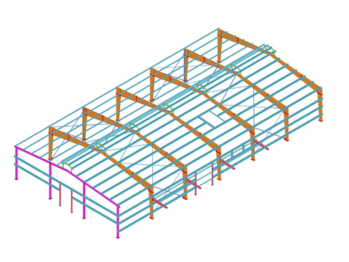
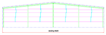
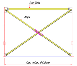
Roof and wall bracings system.
Rod and angle bracings are used as wall and roof bracing system. End wall framing system carries wind load and transfers them through strut purlin and then bracings to the ground. Standard brace rods are rod dia 12, 16, 20, 25 and 32mm.
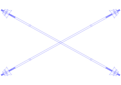
Roof Layout with bracings
